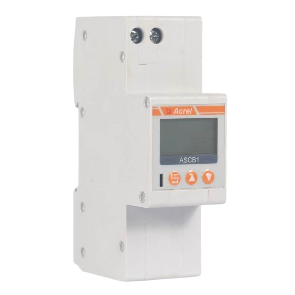
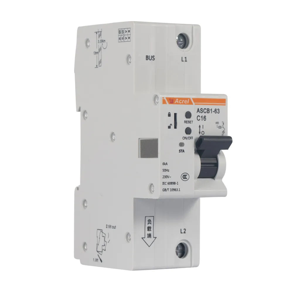
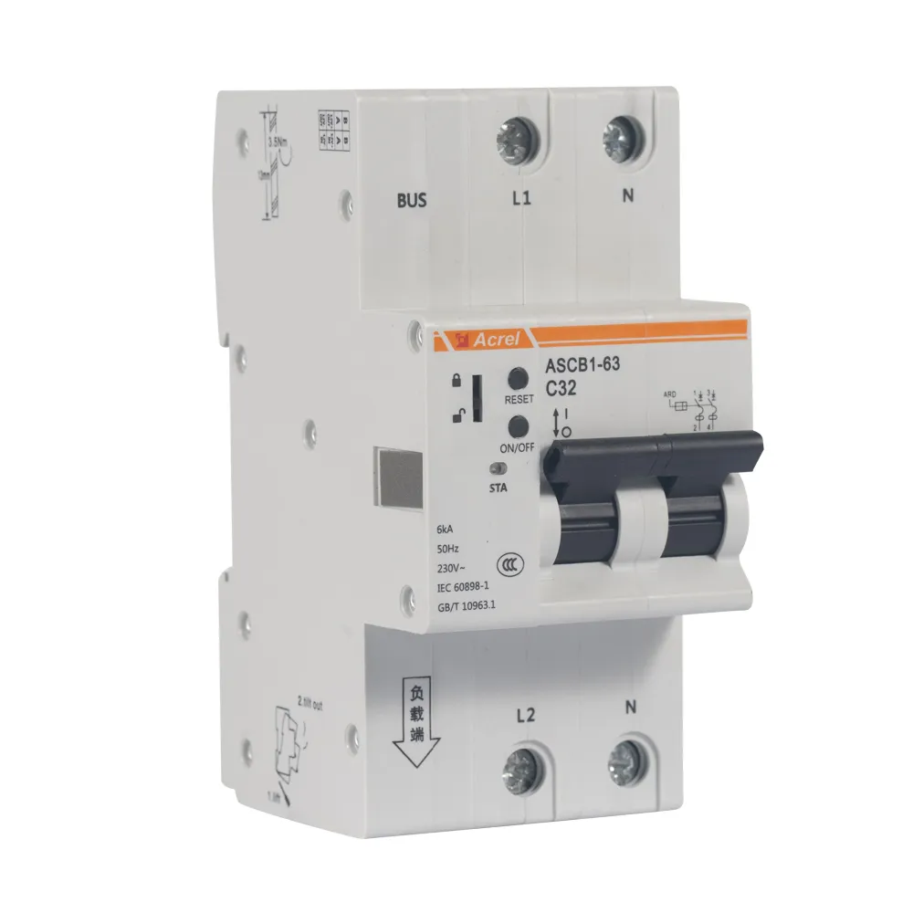
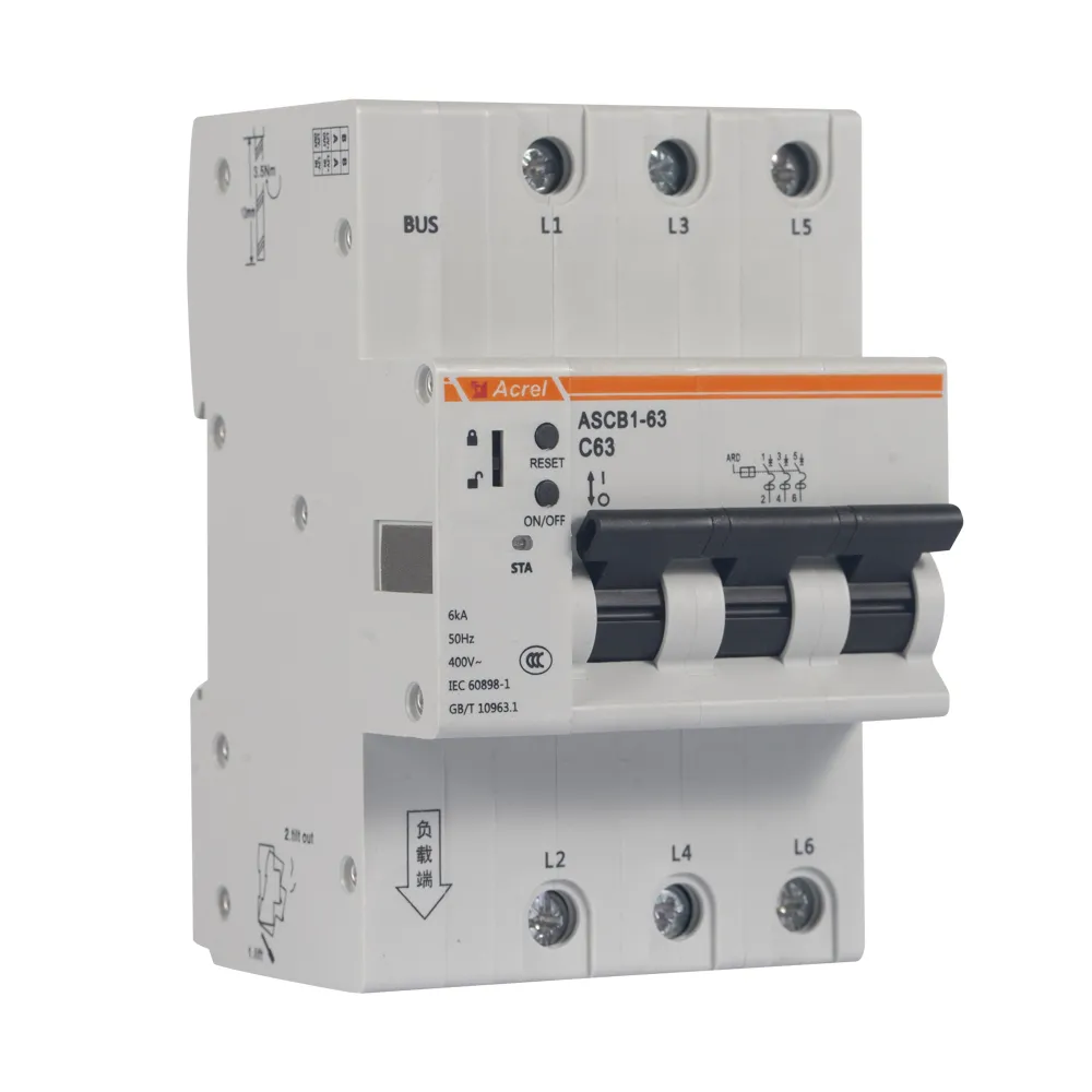
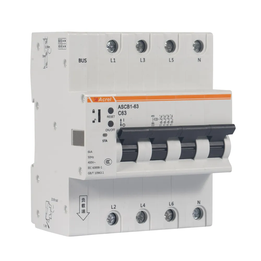
Appearance
Patameter
| | |
| |
| |
| | |
| |
| Up to 20 alarm, fault and action records each |
| |
| |
| -10℃-55℃,24h the average temperature is not higher than 40℃ |
Environmental Requirements | No explosion hazard, no conductive dust, no sufficient corrosion of metal and damaged insulation, no significant vibration |
| At + 40℃, the relative humidity of the air is 50% and can have high relative humidity at lower temperatures |
| |
| |
| Standard 35mm guide rail installation |
Function
ASCB1 Smart Gateway Function |
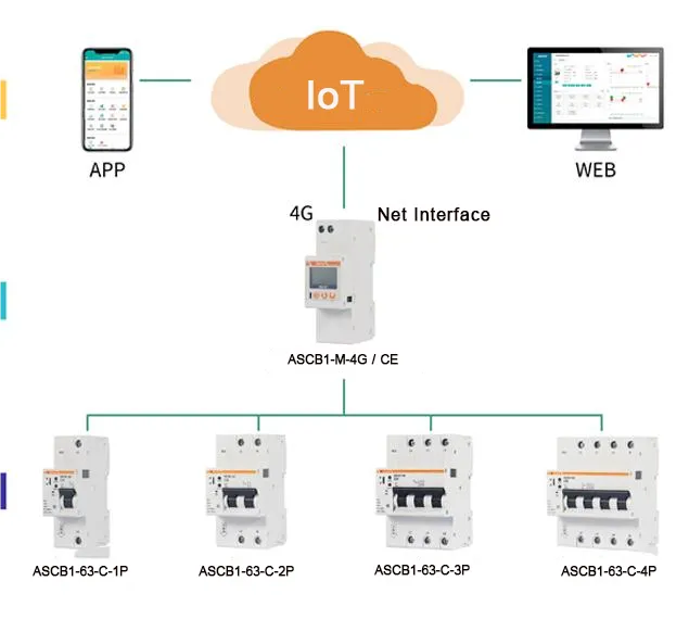
| · Can connect to up to 16 intelligent micro circuit breakers
· See, the real-time data of voltage, current, power, power, temperature and leakage of each intelligent micro circuit breaker
· You can view the fault, alarm and separation status of each intelligent micro circuit breaker
· It can set and control the parameters for each intelligent micro circuit breaker
· Din rail type installation, LCD LCD display
· Support event logging; support RS485 communication
· Support for Ethernet communication. |
| · It can connect to up to 16 smart micro circuit breakers
· Can see the real-time data of voltage, current, power, power, temperature and leakage of each intelligent micro circuit breaker
· Can view the fault, alarm and separation status of each intelligent micro circuit breaker
· It can set and control the parameters for each intelligent micro circuit breaker
· Din rail type installation; LCD LCD display
· Support event logging; support RS485 communication
· Support for 4G network communication |
Wiring
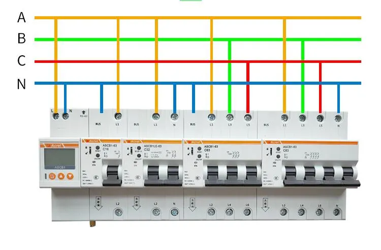
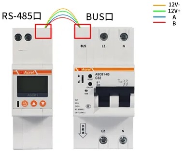
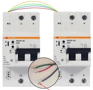
| 
|
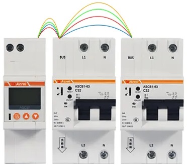
| Step1: Connect the RS485 port on the gateway to the BUS port of the circuit breaker by using the communication cable provided by the gateway | Step2: Insert the barbed side of the connecting wire of the circuit breaker into the external terminal of the previous circuit breaker toward the outside of the terminal, and the colors need to be matched one by one.
|
Typical Connection
FAQ
Q: Can the circuit breaker data be collected through RS485 communication?
A: The circuit breaker has its own RS485 communication interface, and it does not need to be equipped with an ASCB1-M gateway to access the customer system, but the customer needs to provide the circuit breaker with DC12V 12A auxiliary power supply
Q: How many circuit breakers can a gateway carry?
A: 16PCS
Q: How Gateways and Circuit Breakers are Networked?
A: The gateway and the circuit breaker are connected by a 4pin cable, a set of DC12V auxiliary power supply, and a set of RS485 communication lines.
The connection between the circuit breaker and the circuit breaker is the same.
One-key addressing operation through the gateway
Q: Does the circuit breaker need to be equipped with additional accessories?
A: 1. Internally integrate various sensor modules, including: current sensor, leakage transformer, temperature sensor, etc.;
2. The circuit breaker integrates the release function, which can realize remote opening and closing operations;
3. Configure the circuit breaker network cable
![]()
![]()


.png)
.png) EN
EN


